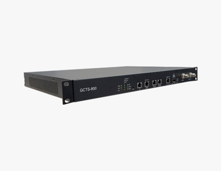
GCTS-800
GPS Signal Generator
 Key Customers
Power Industry/ Rail Industry
ISP Service Providers/ Transmission Network
Basic Informations
| Model | GCTS-800 |
|---|---|
| Type | GPS Signal Generator |
| GPS Signal Output Port Number | 8 Ports (BNC Female, 50 Ω) |
| Applied Fields | Communication equipment in GPS disturbing area - Mobile communication base station - DOTS equipment in transmission-line network - GPS receiving equipment for electric power,railroad, and etc. Communication equipment in GPS shadowed area |
| Size | GCTS-800: 438 × 320 × 44mm, 1U Height, 19” Rack IS2000GPS: 340 × 259 × 44mm, 1U Height, 19” Rack |
 LIST
LISTProduct Overview
Produces reliable GPS L1 signals to external receivers in a situation where receiving GPS signal is not reliable due to disturbance of signals such as GPS Jamming, GPS Spoofing, etc.
Transmits local GPS signals to external receivers during normal use, and produces self-created GPS signals to external receivers when Jamming or Spoofing is detected. In order to maintain accuracy of output signals, it uses KRF-T1/E1 and IS2000GPS information.
GCTS-800 is consisted of GPS signal processing unit (IF/RF up conversion module) and GPS receiving antenna, which allows it to continuously produce reliable GPS signals in conditions where GPS receiving is disturbed. Such technology is extremely useful as there is continuous disturbance on GPS signals from North Korea.
Also, the equipment is linked to GPS server such as PTP GrandMaster to generate and output GPS signal, which allows reception of GPS signal disregarding the shaded areas.
Connection Diagram of GPS Generator

Necessity of GPS Signal Generator
 Requires reliable GPS signal in preparation for GPS Jamming and Spoofing from North Korea
- GPS installed buildings receiving unreliable GPS signals (due to environmental interference)
- Difficulties in installing antennas/cables for new installation in a building
Product Description
Generate GPS Signals
- Self-generate and supply GPS signal under disturbance of GPS signal
- Continuous monitoring on local input GPS signal – Jamming and Spoofing
- Automatic changeover to self-generated GPS signal when local input GPS signal is disturbed
- Automatic changeover to local input GPS signal when it is recovered
- Generates at least 12 GPS L1 satellite signals
- Generates GPS signals based on standard time and satellite tracking
- Acquires location information from local GPS signals
- Synchronized precision timing using local GPS signals
- Maintains high precision clock and synchronized to external input standard signal (KRF-E1)
- Maintains synchronized precision timing with remote IEEE1588 PTP Master
Generate Reliable Signal
- Receives GPS tracking signals from remote GPS server
- System managing and monitoring through EMS
- Receiving KRF T1/E1 and frequency synchronization
- IEEE1588 PTP slave feature available for synchronized timing
- Linkage to PTP Master for synchronized timing
- Automatic changeover to local GPS in occurrence of malfunc-tion
Product Features
GCTS-800
- Generate GPS signals based on standard time and satellite tracking
- Receive local GPS signal
- Maintains high precision time synchronization (<±100ns)
- Receives locational information through local GPS signal
- Synchronizes precision time through local GPS signal
- Maintains precision time synchronization with remote IEEE1588 PTP server
- Synchronizes with KRF-E1/T1 frequency during absence of local GPS signal
- Detection and response to GPS Jamming
- - GPS Jamming detection and Alarm handling feature
- - Collects GPS track information from remote GPS server during Jamming
- - Maintains high precision clock through locking into external reference time
- - Time information maintains initial GPS time or uses IEEE1588 information
- - Outputs E1 signal that is synchronized to internal high precision clock
GPS Server
- Receives GPS tracking and GPS status information
- Refreshes satellite tracking information in 10 seconds interval
- Able to deliver satellite tracking information when requested by GPS generator
- Monitoring feature on receiving GPS signals
- Delivers status information to EMS server
- Provides IEEE1588v2 PTP GrandMaster clock
- - Provides high precision clock
- - Time : < 100 ns
- - Frequency : 1 × 10-11 (ITU-T G.811)
- - Supports various modes (Unicast, Multicast, and Mixed-mode)
- - Provides PTP Service to up to 512 Unicast Slaves
Applied fields
- Communication equipment in GPS disturbing area
- - Mobile communication base station
- - DOTS equipment in transmission-line network
- - GPS receiving equipment for electric power, railroad, etc
- Communication equipment in GPS shadowed area
Compliance Standard
IEEE
- IEEE1588v2-2008
- IEEE802.1Q VLAN
- IEEE802.1p LAN Layer2 QoS/CoS Protocol
ITU-T
- ITU-T G.8261, G.8262, G.8264, G.8265.1
- ITU-T G.8272, G.8275.1, G.8275.2
- ITU-T G.811, G.812
IETF
- RFC 792, RFC 2474, RFC 2616
Specification
- *See the IS2000 data sheets
Mechanical
- GCTS-800 : 438 x 320 x 44 mm, 1U height, 19” RACK
Environmental
- Operating temperature : 0 ~ +50ºC
- Operating humidity : 0 ~ 90% at RH non-condensing
- Storage temperature : 0 ~ +70ºC
Power Supply
- Option : AC or DC input
- AC input : 90 ~ 264Vac, 50Hz/60Hz
- DC input : -42 ~ -56Vdc
- Power consumption : Max 40W
Local GPS Lock Accuracy
- * Accuracy under locked to GNSS at operating temp.
- Time : <±100ns
- Frequency : 1x10-11 (ITU-T G.811)
[I/O Port in Front Panel]
Monitoring
- 1PPS Output : 50Ω BNC [Female]
- 10MHz clock output : 50Ω BNC [Female]
- CIT : RS232, RJ45
- Management : 10/100Mbps Ethernet, RJ45
- BITS IN : T1/E1 Input, RJ45, 120 Ω, x2
- PTP Interface : 100M/1000Mbps Ethernet combo
- Combo Style : Copper RJ45 and Fiber SFP
[I/O Port in Front Panel]
- AC Option : IEC60320 C14 socket
DC Option : 1776692(MSTB 2,5/2-GF), Phoenix
* Mating P/N: 1786831(MSTB 2,5/2-STF), Phoenix
GPS input
- Connector : 50Ω BNC [Female] x1
- Voltage feed to GNSS antenna from GPS receiver
GPS output
- Connector : 50Ω BNC [Female] x8
- Input voltage from receivers feed to GPS antenna
Management
- CLI
- Telnet for remote system control
- EMS
Network Support
- VLAN (802.1Q, 802.1p), Q-in-Q
- IPv4 DSCP
- ICMP (RFC792)
- IEEE1588v2 PTP slave
- SNMP v2c, v3 for NMS

- Springwave Co.,Ltd
- 2F, Daechang Building 10-3, Hwangsaeul-ro 258beon-gil, Bundang-gu, Seongnam-si, Gyeonggi-do, Korea 13595
- E-mail : support@springwave.co.kr
- Tel : +82-31-272-2112
- Fax : +82-31-263-6569